Advanced FEA Assemblies | Foundations + Assemblies | areaFEA
ADVANCED FEA PROGRAM

Take Your FEA Skillsto the NEXT LEVEL

From FEA Fundamentals to Advanced Assembly Simulations

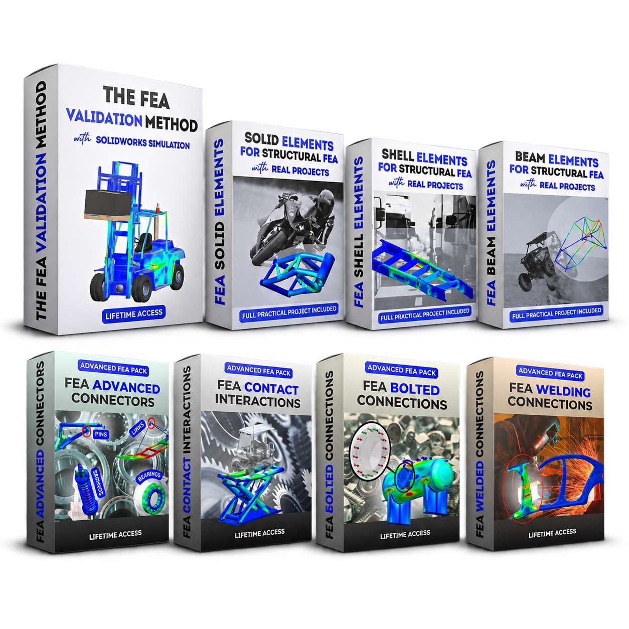
Build a solid FEA foundation, then take your skills further by learning to simulate complex assemblies and tackle more challenging engineering problems.
  • Understand the reasoning behind every simulation decision
  • Practice on real engineering projects
  • Learn from an FEA engineer actively working in the industry
GET ADVANCED FEA PROGRAM
Lifetime access14-day money-back guaranteeDirect support inside the academy
Advanced FEA Program — eight practical FEA trainings
★★★★★
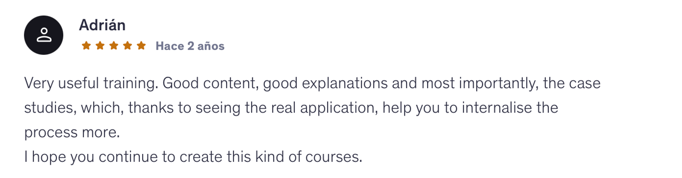
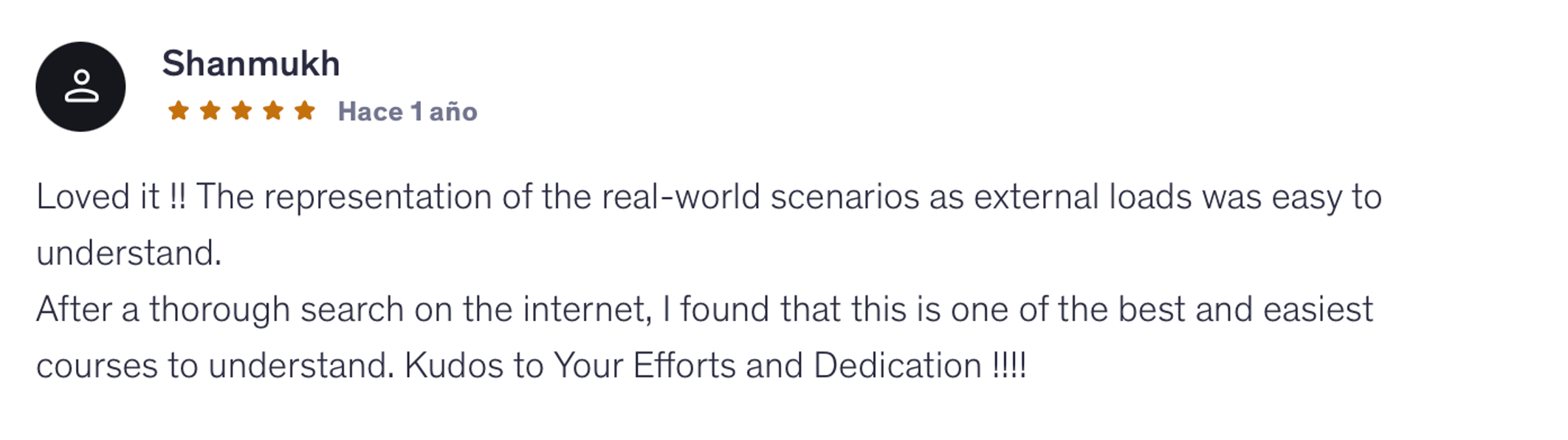
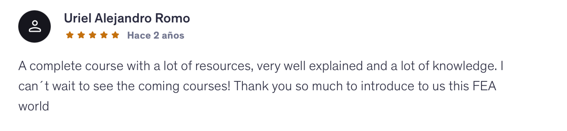
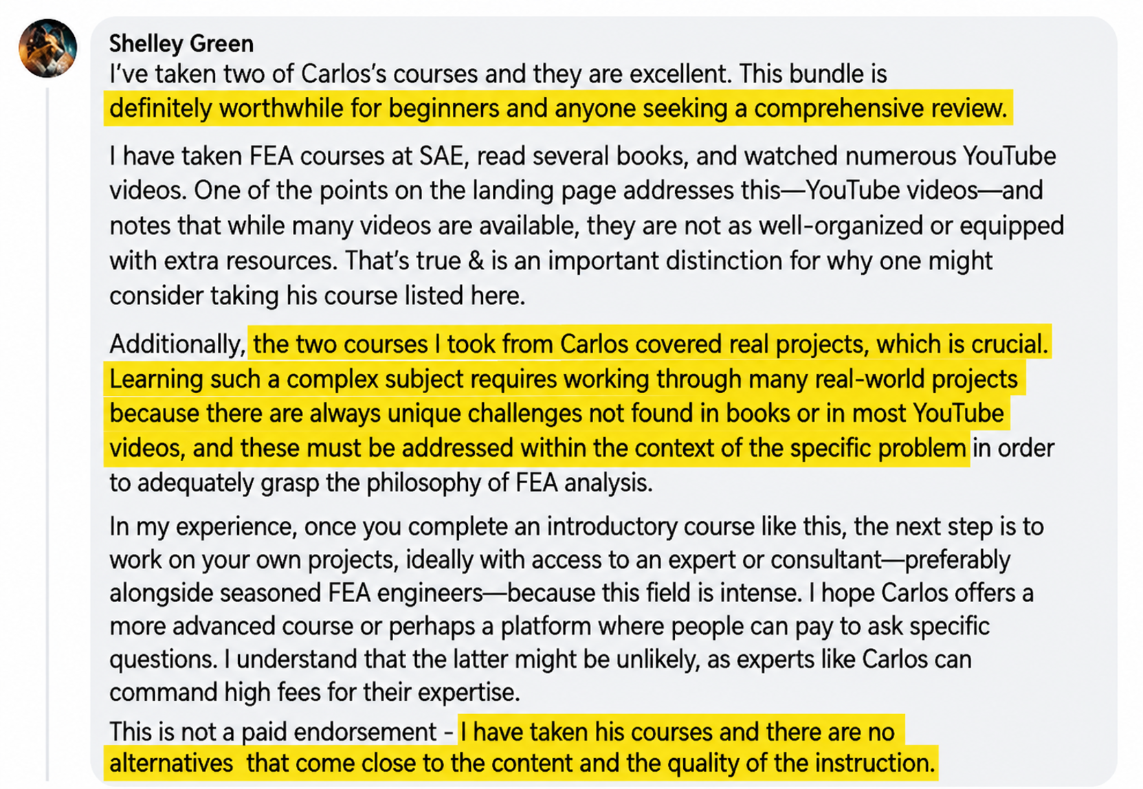
“The two courses I took from Carlos covered real projects, which is crucial. […] There are no alternatives that come close to the content and the quality of the instruction.”
Shelley GreenareaFEA student
14+YEARS OF FEA SIMULATION EXPERIENCE
2,300+ENGINEERS TRAINED WORLDWIDE
300+STUDENT REVIEWS
4.8/5AVERAGE COURSE RATING

THE PROBLEM

  • Learning FEA topics in isolation
  • Copying software steps without knowing WHY
  • Stuck on simple exercises
  • Getting lost in complex simulations
  • Not knowing if your results are right
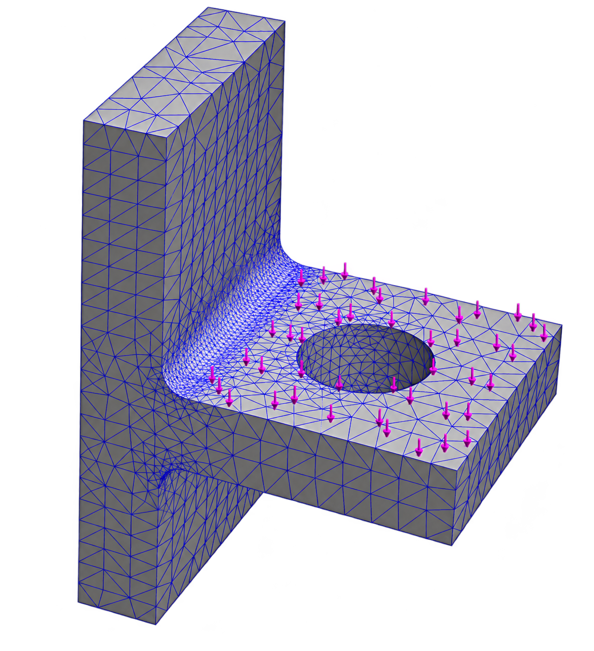
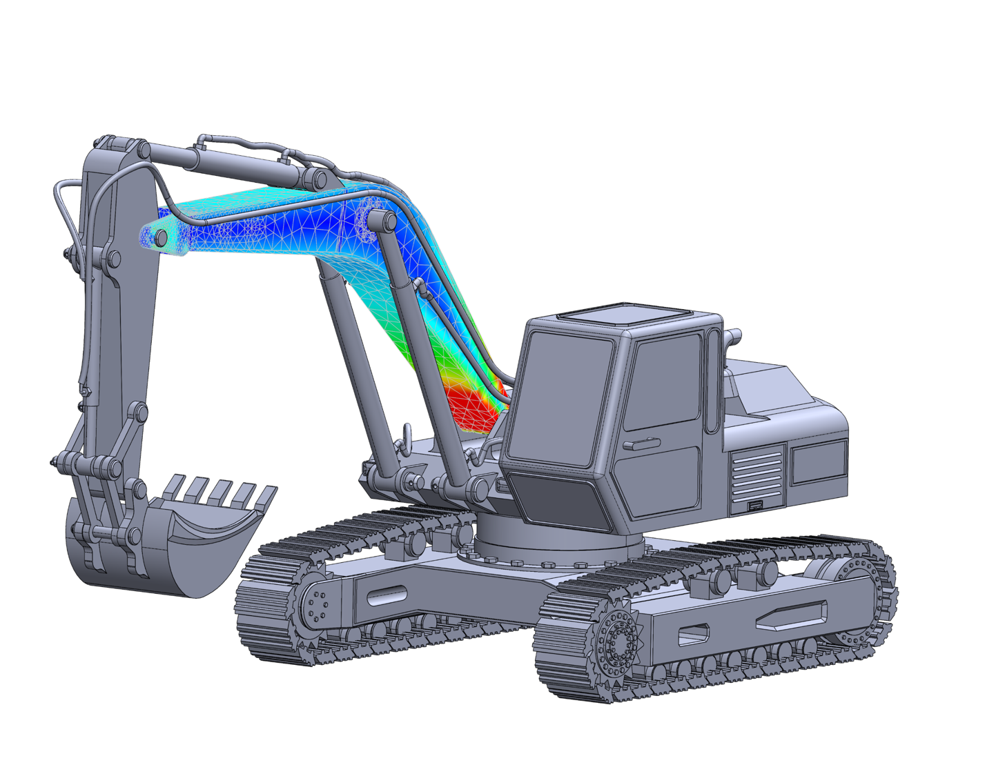
FEA model illustrating the problem

THE SOLUTION

  • Understand WHY behind every decision
  • Practice on real engineering projects
  • Learn from an active FEA expert
  • Build your own FEA portfolio
  • Enjoy learning FEA through real projects
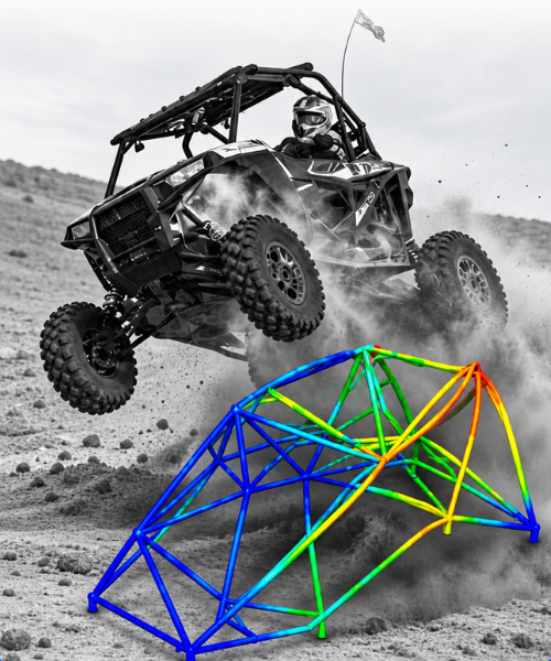
Real-world engineering simulation
THE areaFEA METHOD

Learn FEA Through Real Engineering Problems.

Real engineering problems don’t tell you which element type to use, how to model a connection, or whether your results make sense.

That’s what you’ll learn to figure out.

The goal isn’t to reproduce a simulation. It’s to understand how to approach the next one.

THE ADVANCED FEA LEARNING PATH

From FEA Fundamentals to
Real Engineering Assemblies

Build your simulation FEA foundation, apply it to three real engineering projects, and move from individual components to more complex assemblies.

01

Build Your Simulation Foundation

Learn the full FEA workflow and understand the decisions behind each stage, from geometry preparation to results validation.
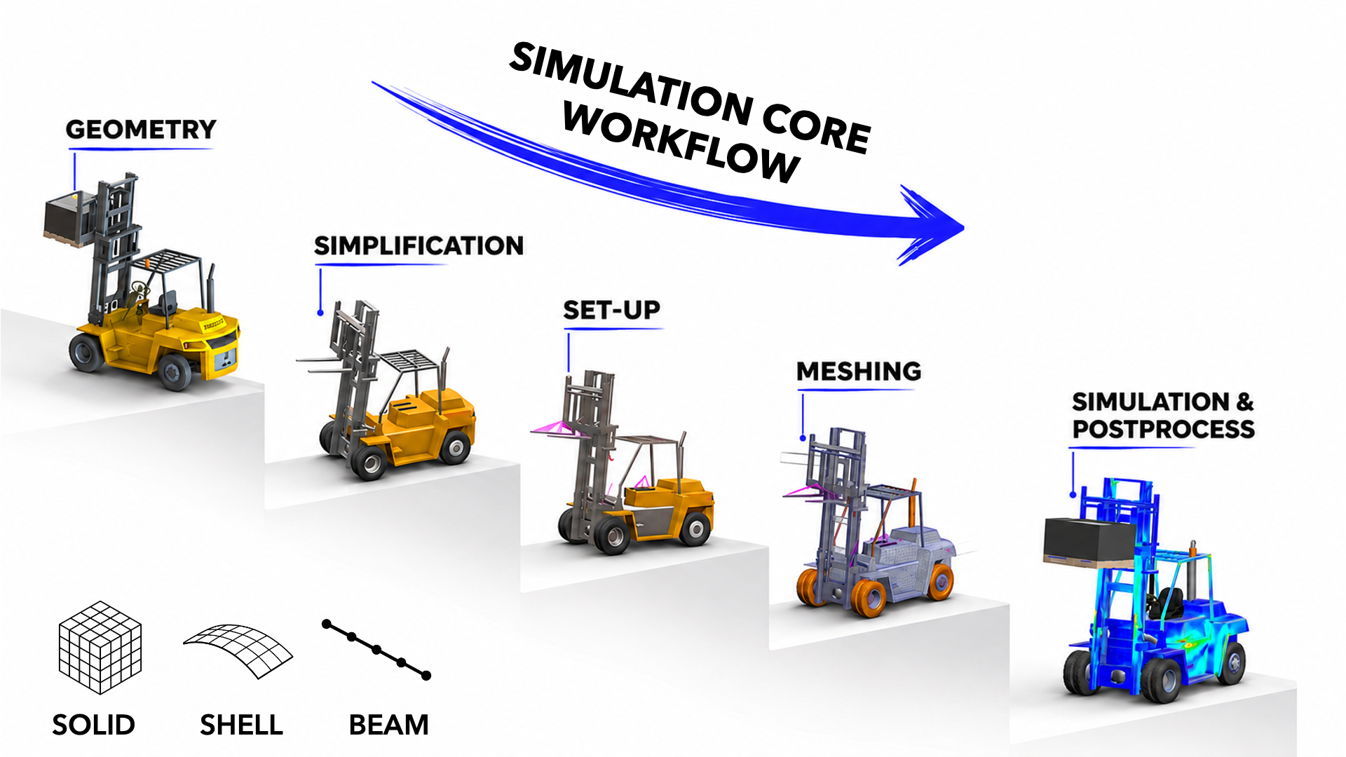
The Complete Simulation Workflow

Simulation core workflow: geometry, simplification, setup, meshing and postprocessing
1Geometry Optimization
Before any simulation can run, the geometry has to be clean, not just visually but in an engineering sense. You'll learn to identify and remove features that can affect FEA results: tiny fillets, redundant faces, and unnecessary geometric details.
You'll use Split Lines to define load application zones and Reference Geometry to set up precise coordinate systems. This step helps turn a CAD model into a simulation-ready model.
2Materials Library
It's easy to accept default material properties and move on. But are they right for your simulation?
You'll build and maintain your own custom materials library with properly defined mechanical properties: Young's modulus, Poisson's ratio, and yield strength.
When a result changes because of a material assumption, you'll understand why and how to address it.
3Boundary Conditions
This is one of the biggest challenges in FEA, and where this program delivers the most value.
You'll learn to translate real-world physics into simulation conditions: how a vehicle's weight becomes a static load, how a road bump becomes a dynamic force, and how supports and joints constrain a structure without over-constraining the model.
You'll apply load cases the way they're applied in automotive and aerospace validation, not just through idealized textbook examples.
4Meshing
Meshing isn't about making the model look detailed. It's about getting reliable results without unnecessary computation time.
You'll learn Standard vs. Curvature-based meshing, how to apply local mesh controls at stress concentration zones, and how to use aspect ratio as an indicator of mesh quality.
You'll run convergence checks to assess whether your results are sufficiently mesh-independent and avoid unnecessary computation time.
5Analysis & Solver
Running a simulation isn't just pressing a button and waiting.
You'll learn to select and configure the appropriate solver options for your problem and diagnose setup errors that can lead to misleading results.
You'll use the Load Case Manager to run and compare multiple scenarios efficiently, as you would in a professional simulation workflow.
6Validation
A simulation result is only as good as your ability to validate it.
You'll learn to read von Mises stress plots, displacement fields, and safety factor distributions with real engineering judgment, not just color-map intuition.
You'll compare results across element types, cross-check against hand calculations where possible, and develop the engineering judgment to question and explain your results.
This is how you start thinking like a simulation engineer, not just a software user.
02

Apply the FEA Foundations to Real Engineering Projects

Use Solid, Shell and Beam elements to analyze a motorcycle, truck and buggy chassis.
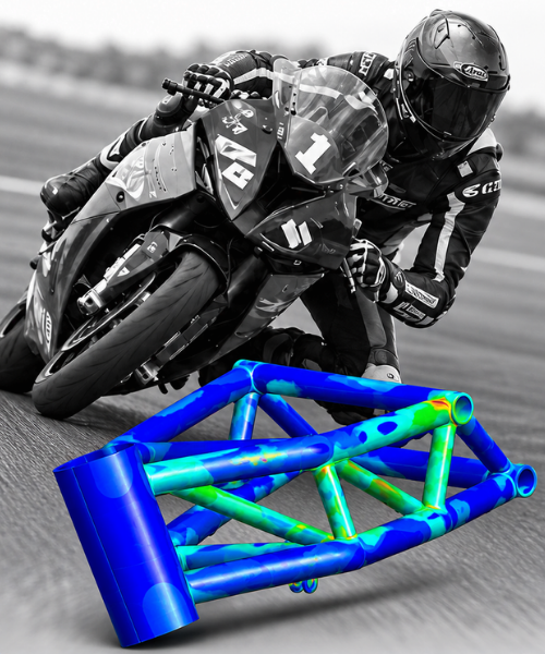
Solid Elements — motorbike chassis project

Solid Elements

Analyze 3D parts and assess stresses.
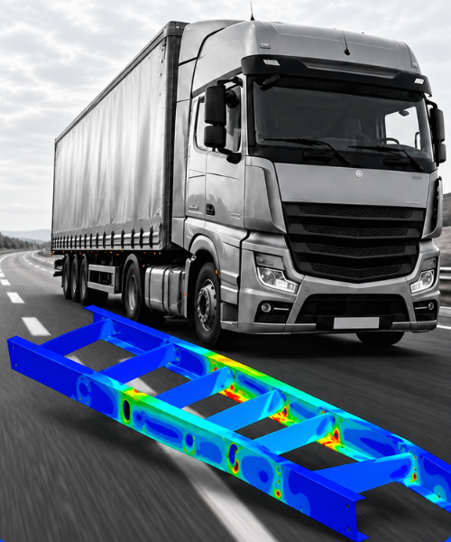
Shell Elements — truck chassis project

Shell Elements

Simulate thin-walled structures.

Beam Elements — buggy chassis project

Beam Elements

Analyze structural frames and loads.

03

Contact Interactions

Understand how components interact and transfer loads within an assembly.
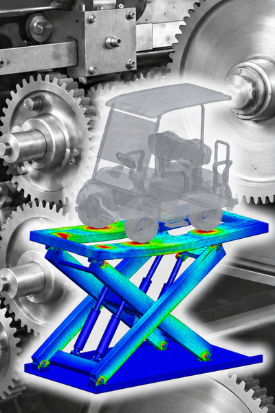
05 · Contacts
04

Bolted Connections

Learn how to model and analyze bolted joints in mechanical assemblies.
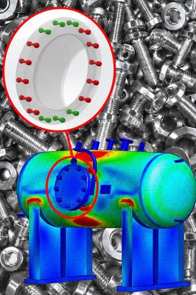
06 · Bolted Connections
05

Welding Connections

Learn to represent welded connections and evaluate their structural behavior.
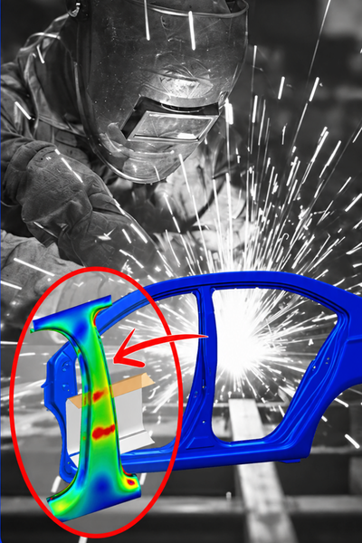
07 · Welded Connections
06

Advanced Connectors

Model pins, springs, links and bearings to represent different mechanical connections.
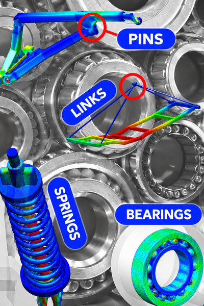
08 · Advanced Connectors
THE LEARNING EXPERIENCE

Learn at Your Own Pace. Apply What You Learn.

Everything you need to learn, practice, and get help whenever you need it.

Lifetime Access

Learn on your schedule. Revisit any lesson whenever you need it.
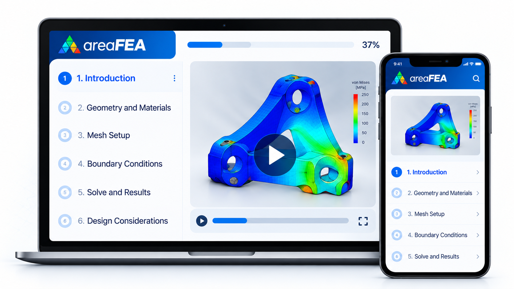
Lifetime access to the areaFEA training on laptop and mobile

Project Files & Resources

Download the models and files to run every simulation yourself.
Project files and resources for the areaFEA training

Direct Instructor Support

Stuck on a simulation? Ask your instructor directly inside the academy.
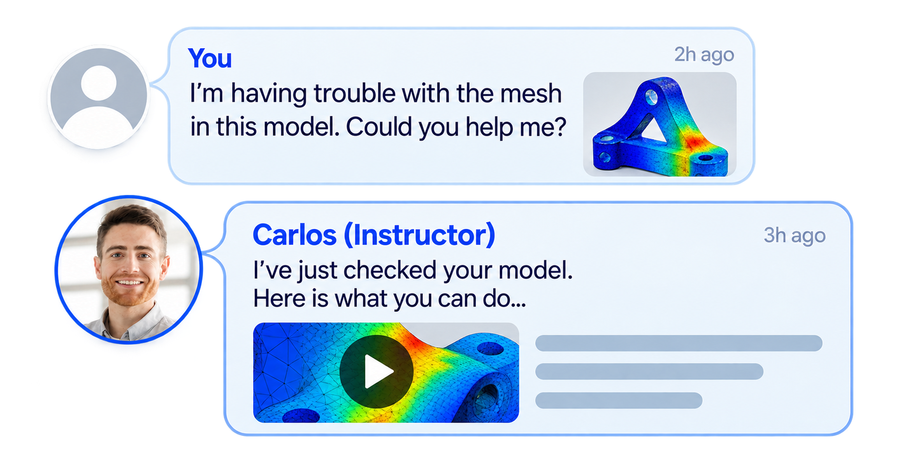
Direct instructor support inside the areaFEA Academy

Certificates of Completion

Earn certificates for completed training and showcase them on your CV or LinkedIn.
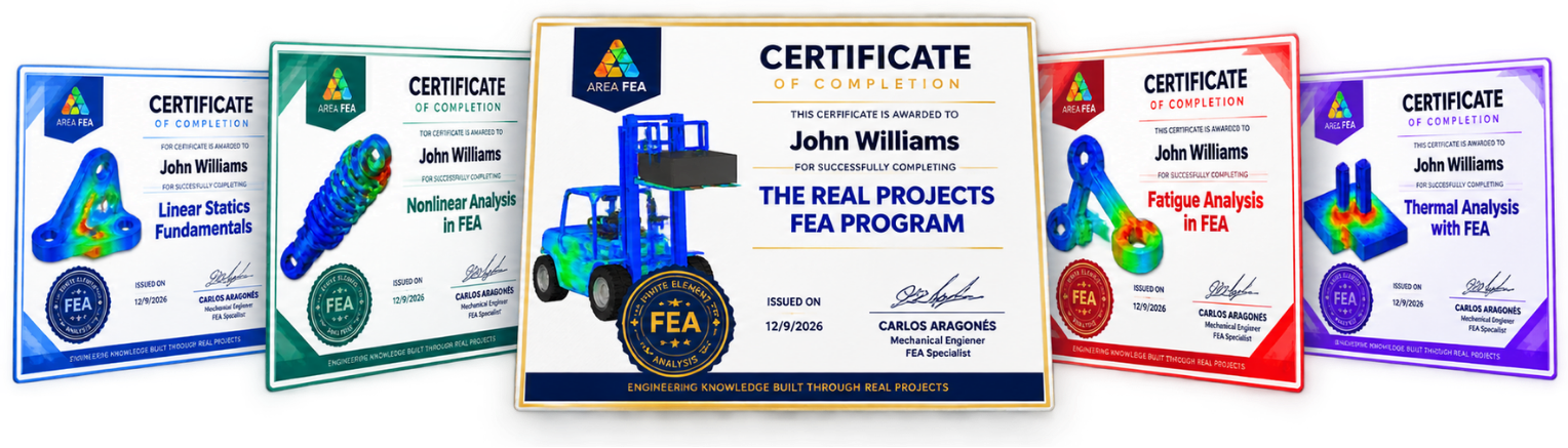
areaFEA certificates of completion
EXPLORE THE PROGRAM

See Exactly What You'll Learn

Open a step to explore the lessons and real engineering projects included.

1The FEA Validation WorkflowCore concepts, the simulation process, and FEA with shell and beam elements.
Introduction & Theory KEY Points
  • Welcome & About the Course
  • Intro to FEM (Finite Element Method)
  • CAE Software in the Market
  • SolidWorks Simulation: Inside the CAE Software
  • Preparing the Geometry: PRE-PROCESS
  • Preparing the Geometry: SPLIT LINE
  • Preparing the Geometry: REFERENCE GEOMETRY (Coordinate Systems Definition)
  • MATERIALS Definition: Create Your Own Library
FEA Simulation Process
  • Boundary Conditions: DEFINITION
  • Boundary Conditions: CONSTRAINTS
  • Boundary Conditions: LOAD CASES in Vehicle Environment
  • Boundary Conditions: LOAD CASES in FEA
  • Meshing: STANDARD
  • Meshing: CURVATURE
  • Meshing: CONTROLS
  • SOLVER: How to Choose It?
  • SOLVER: Define and Run the Simulation
  • Results Review: Post-Process PART I, II & III
  • Duplicate and Compare Different Simulations
  • The Power of the Load Case Manager
FEA with SHELL Elements
  • SHELL ELEMENTS: Theory
  • SHELL ELEMENTS: Pre-Process (Surfaces Preparation)
  • SHELL ELEMENTS: Definition in Simulation
  • SHELL ELEMENTS: Simulation Set-Up
  • SHELL ELEMENTS: Meshing
  • SHELL ELEMENTS: Results Review (Post-Process)
FEA with BEAM Elements
  • BEAM ELEMENTS: Theory
  • BEAM ELEMENTS: Geometry Description
  • BEAM ELEMENTS: Definition in Simulation
  • BEAM ELEMENTS: Joints
  • BEAM ELEMENTS: Constraints
  • BEAM ELEMENTS: External Loads
  • BEAM ELEMENTS: Meshing
  • BEAM ELEMENTS: Results Review (Post-Process Part I & II)
2Apply the Foundations to Real Engineering ProjectsThree complete engineering projects using solid, shell and beam elements.
Motorbike Chassis FEA · Solid Elements
  • BIKE CHASSIS: Project Presentation
  • BIKE CHASSIS: Geometry Preparation Part I & II
  • BIKE CHASSIS: Element Definition & Materials
  • BIKE CHASSIS: Constraints and Contacts Intro
  • BIKE CHASSIS: External Loads Part I & II
  • BIKE CHASSIS: Meshing
  • BIKE CHASSIS: Results Review (Post-Process)
  • BIKE CHASSIS: Complete Frequency Analysis
Truck Chassis FEA · Shell Elements
  • TRUCK CHASSIS: Project Presentation
  • TRUCK CHASSIS: Geometry Preparation Part I & II
  • TRUCK CHASSIS: Shell Elements Definition & Materials
  • TRUCK CHASSIS: Constraints and Contacts Revision
  • TRUCK CHASSIS: External Loads for Chassis Validation
  • TRUCK CHASSIS: Meshing & Solver
  • TRUCK CHASSIS: Results Review (Post-Process)
Buggy Chassis FEA · Beam Elements
  • BUGGY CHASSIS: Project Presentation
  • BUGGY CHASSIS: Geometry Preparation
  • BUGGY CHASSIS: Beam Elements Definition & Materials
  • BUGGY CHASSIS: Joints Validation
  • BUGGY CHASSIS: Constraints and Loads for Max Bump Event
  • BUGGY CHASSIS: Beam Elements Meshing
  • BUGGY CHASSIS: Max Bump Results Review (Post-Process)
  • BUGGY CHASSIS: RollOver Event Simulation
3Contact InteractionsContact types, model setup and the scissor lift project.
INTRODUCTION
  • WELCOME
  • ABOUT THE COURSE
CONTACT INTERACTIONS IN FEA
  • What is a Contact Interaction in FEA?
  • Software Configuration Options
  • Contact Interaction. Type BONDED
  • Contact Interaction. Type CONTACT
  • Contact Interaction. Type FREE
  • Contact Interaction. Type SHRINK FIT
  • Contact Interaction. Type VIRTUAL WALL
Interactions type BONDED
  • Global Interaction
  • Compatible vs Incompatible Mesh
  • Gap Adjustment
  • Components interaction
  • Local Interaction. Select Other
  • Interaction Hierarchy
Interactions type CONTACT
  • Contact Pairs Tips
  • Interaction Calibration. Gap Adjustments
  • Contact Offset
  • Non Convergence Scenario
  • Restrictions for Convergence
  • Manual vs Automatic Interaction Definition
PROJECT: Scissor Lift System FEA
  • SCISSOR PROJECT. Exploded Views for Interactions
  • SCISSOR PROJECT. Interactions Definitions
  • SCISSOR PROJECT. Results Post-Processing
  • SCISSOR PROJECT. Contact Pressure Analysis
4Bolted ConnectionsBolted joint modeling and practical connection projects.
INTRODUCTION
  • WELCOME
  • ABOUT THE COURSE
BOLTED CONNECTIONS IN FEA
  • What is a connection?
  • Type of connections in FEA
  • Bolted Connection in FEA
  • Bolted Connection: Preparing the connection
  • Bolted Connection: COUNTERBORE WITH NUT. Part I
  • Bolted Connection: COUNTERBORE WITH NUT. Part II
  • Bolted Connection: COUNTERSINK WITH NUT
  • Bolted Connection: COUNTERBORE SCREW
  • Bolted Connection: COUNTERSINK SCREW
  • Bolted Connection: FOUNDATION BOLT
ADVANCED BOLTED CONNECTION IN FEA
  • Bolts in Tension
  • Bolts in Shear
  • Bolts Series. Multiple Parts Connected
  • PRELOAD. Definition
  • PRELOAD. Simulation
  • PRELOAD. Results Postprocessing
  • PRELOAD. By TORQUE
PROJECT 01. Pressure Vessel FEA
  • PRESSURE VESSEL. Project Description
  • PRESSURE VESSEL. Holes Series. Define Geometry
  • PRESSURE VESSEL. Hole Series. Automatic Bolts
  • PRESSURE VESSEL. Hole Series. Simulation Setup
  • PRESSURE VESSEL. Hole Series. Results Post-Process
  • PRESSURE VESSEL. Smart Fasteners. Define Geometry
  • PRESSURE VESSEL. Smart Fasteners. Automatic Bolts
  • PRESSURE VESSEL. Smart Fasteners. Simulation SetUp
  • PRESSURE VESSEL. Smart Fasteners. Results Post-Process
PROJECT 02. Solar Panel FEA
  • SOLAR PANEL. Project Description
  • SOLAR PANEL. Preparing the Geometry
  • SOLAR PANEL. Simulation SetUp
  • SOLAR PANEL. Bolted Connections
  • SOLAR PANEL. Simulation SetUp. Part II
  • SOLAR PANEL. Simulation Results PostProcess
5Welding ConnectionsWeld representations, spot weld connectors and engineering applications.
INTRODUCTION
  • WELCOME
  • ABOUT THE COURSE
WELDING CONNECTIONS IN FEA
  • What is Welding?
  • Types of Welding. The Heat Affected Zone (HAZ)
  • Welding in FEA. Methodologies
  • Solid Elements Welds. No Weld Geometry
  • Solid Elements Welds. Weld Geometry
  • Shell Elements Welds. No Weld Geometry
  • Shell Elements Welds. Fillet, Double-sided
  • Shell Elements Welds. Fillet, Single-sided
  • Shell Elements Welds. Groove, Double-sided
  • Shell Elements Welds. Groove, Single-sided
SPOT WELD CONNECTORS IN FEA
  • What is spot welding?
  • Applications of spot welding.
  • How to treat them in (FEA).
  • How to evaluate them correctly
PROJECT 01: Flat Back Elbow FEA
  • FLAT BACK ELBOW. Project Description
  • FLAT BACK ELBOW. Define Geometry. Surfaces
  • FLAT BACK ELBOW. Define Geometry. Spot Welds Locations
  • FLAT BACK ELBOW. Spot Welds FEA Simulation Set-up. PartI
  • FLAT BACK ELBOW. Spot Welds FEA Simulation Set-up. PartII
  • FLAT BACK ELBOW. Spot Welds Results Post-Process
PROJECT 02: Forklift Front Axle FEA
  • FRONT AXLE. Project Description
  • FRONT AXLE. Define Geometry for Arc Welds
  • FRONT AXLE. FEA Simulation Set-Up for Welding. PartI
  • FRONT AXLE. FEA Simulation Set-Up for Welding. PartII
  • FRONT AXLE. Welding Convergence Issues
  • FRONT AXLE. Edge Weld Results Post-Process
PROJECT 03: Car B-Pillar FEA
  • CAR B-PILLAR. Project Description
  • CAR B-PILLAR. Define Geometry. Spot Welds Location
  • CAR B-PILLAR. Define Geometry. Crash Barrier Definition
  • CAR B-PILLAR. FEA Simulation Set-Up
  • CAR B-PILLAR. Convergence Issues
  • CAR B-PILLAR. Spot Weld Results Post-Process
6Advanced ConnectorsSprings, links, pins and bearings used in mechanical assemblies.
INTRODUCTION
  • WELCOME
  • ABOUT THE COURSE
ADVANCED CONNECTORS
  • SPRING Connector in FEA
  • LINK Connector in FEA
  • PIN Connector in FEA
  • BEARING Connector in FEA
SPRING CONNECTORS IN FEA
  • SPRING Connector in FEA
  • TENSION GAUGE PROJECT. Spring Connector in Tension
  • TENSION GAUGE PROJECT. Spring Connector. K Distributed vs. Total
  • TENSION GAUGE PROJECT. Spring Connector. Two Locations
  • CULTIVATOR ARM PROJECT. Spring Connector in Compression. Interactions
  • CULTIVATOR ARM PROJECT. Spring Connector in Compression. FEA Definition
  • CULTIVATOR ARM PROJECT. Spring Connector in Compression. Results
  • CULTIVATOR ARM PROJECT. Spring Connector in Compression. PRELOAD
  • CULTIVATOR ARM PROJECT. Spring Connector in Compression. SHEAR STIFFNESS
LINK CONNECTORS IN FEA
  • LINK Connector in FEA
  • LINK SYSTEM PROJECT. Real Link. AUTOMATIC INTERACTIONS
  • LINK SYSTEM PROJECT. Real Link. Simulation
  • LINK SYSTEM PROJECT. Real Link. Results
  • LINK SYSTEM PROJECT. LINK CONNECTOR
  • CHASSIS LIFT PROJECT. LINKAGE ROD. Definition
  • CHASSIS LIFT PROJECT. LINKAGE ROD. Simulation Results
  • CHASSIS LIFT PROJECT. LINKAGE ROD. Chassis & Suspension Components
  • CHASSIS LIFT PROJECT. LINKAGE ROD. Mass Adjustment
  • CHASSIS LIFT PROJECT. LINKAGE ROD. Total Restrictions
PIN CONNECTORS IN FEA
  • PIN Connector in FEA
  • COUPLING SYSTEM PROJECT. Pin Interactions
  • COUPLING SYSTEM PROJECT. Pin With Retaining Ring: No translation
  • COUPLING SYSTEM PROJECT. Pin Results
  • COUPLING SYSTEM PROJECT. Pin With key: No rotation
  • BOOM STRUCTURE PROJECT. Pin Advanced Interactions
  • BOOM STRUCTURE PROJECT. Pin Combination
  • BOOM STRUCTURE PROJECT. Pin Results. Complete Project
BEARING CONNECTORS IN FEA
  • BEARING Connector in FEA
  • CRANK SHAFT PROJECT. Bearing Configuration
  • CRANK SHAFT PROJECT. Bearing Results
  • CRANK SHAFT PROJECT. Bearing Self Alignment
  • CRANK SHAFT PROJECT. Bearing Flexible Configuration
  • CRANK SHAFT PROJECT. Bearing Stabilize Shaft Rotation
TAKE YOUR SIMULATIONS FURTHER

Why the Advanced FEA Program
Will Be a GAME-CHANGER for You

Build the practical skills to move from individual components to realistic engineering assemblies.
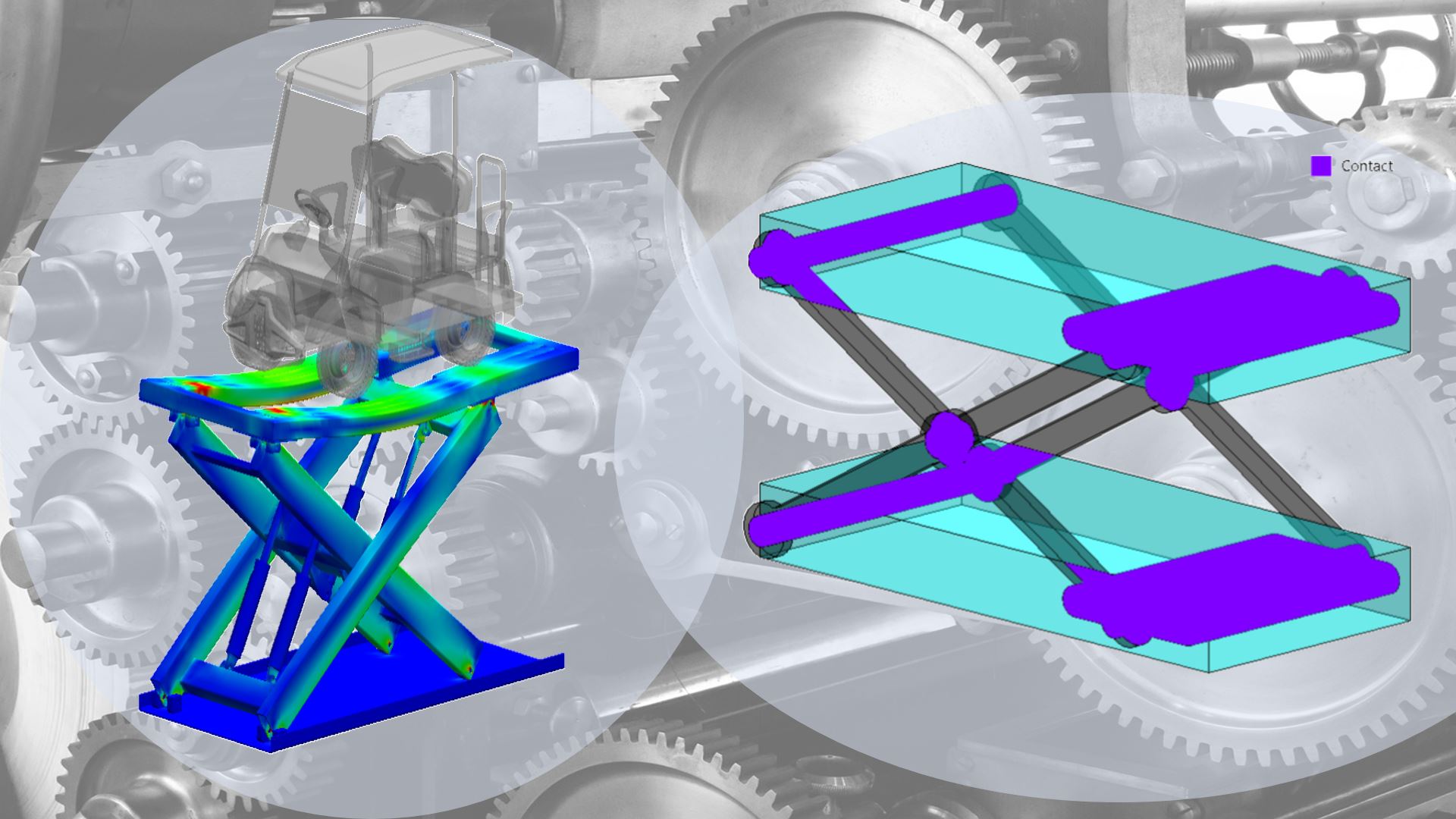
Realistic Assemblies

Realistic Assemblies

Simulate complex, real-world structures with precision.
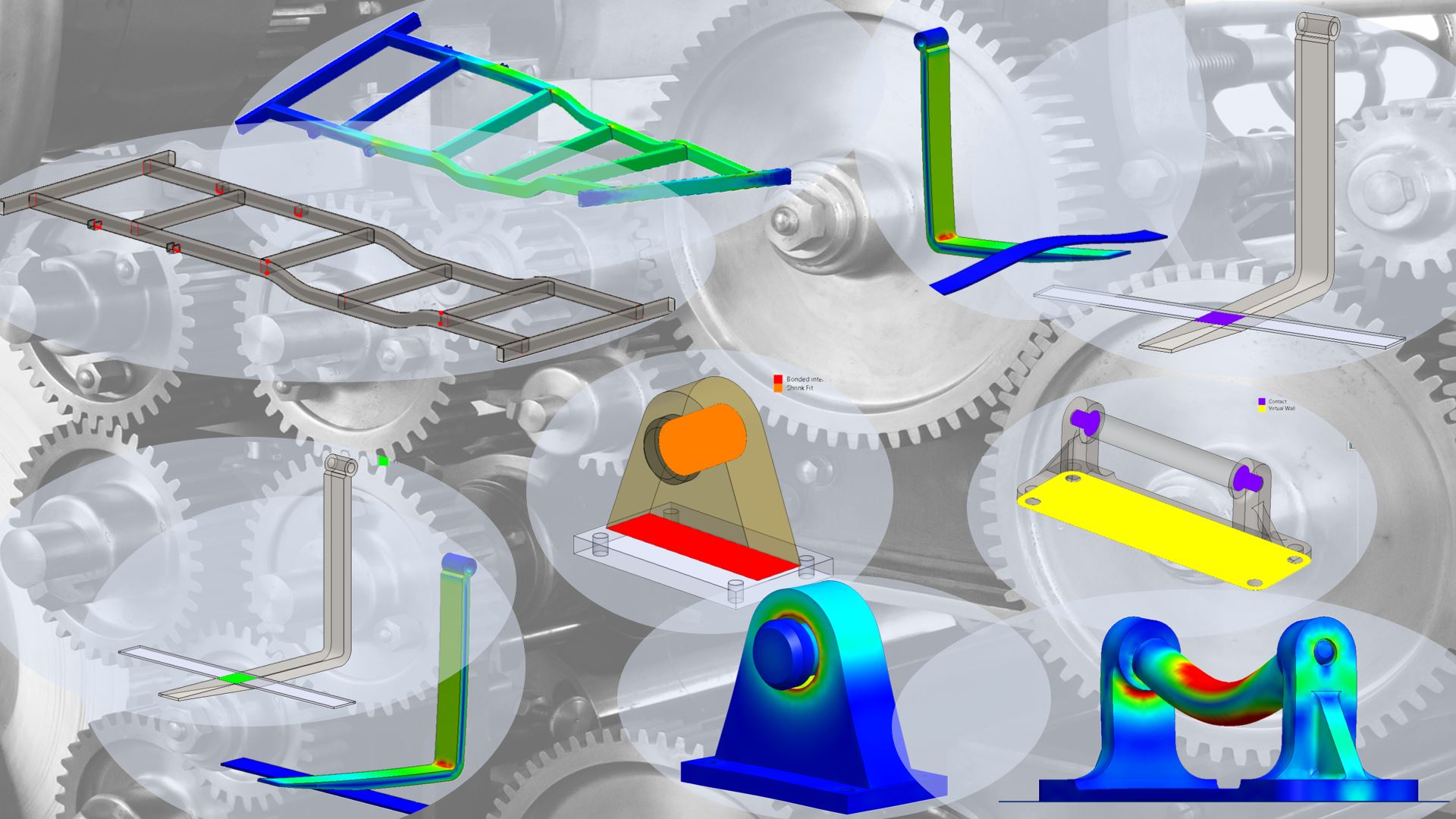
More Real Examples

More Real Examples

Work on industrial engineering problems, beyond simplified exercises.
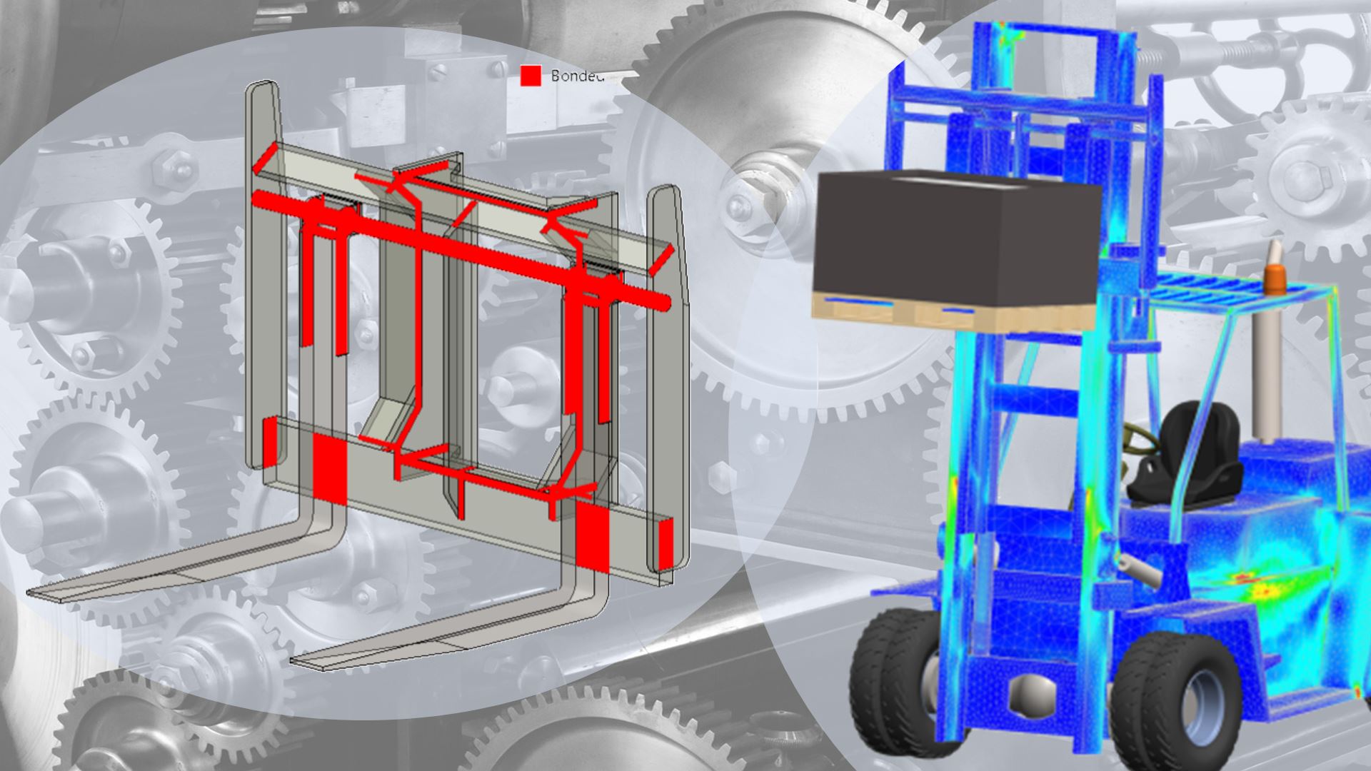
The Right Contact Setup

The Right Contact Setup

Choose the right contact setup for each scenario to obtain accurate results.
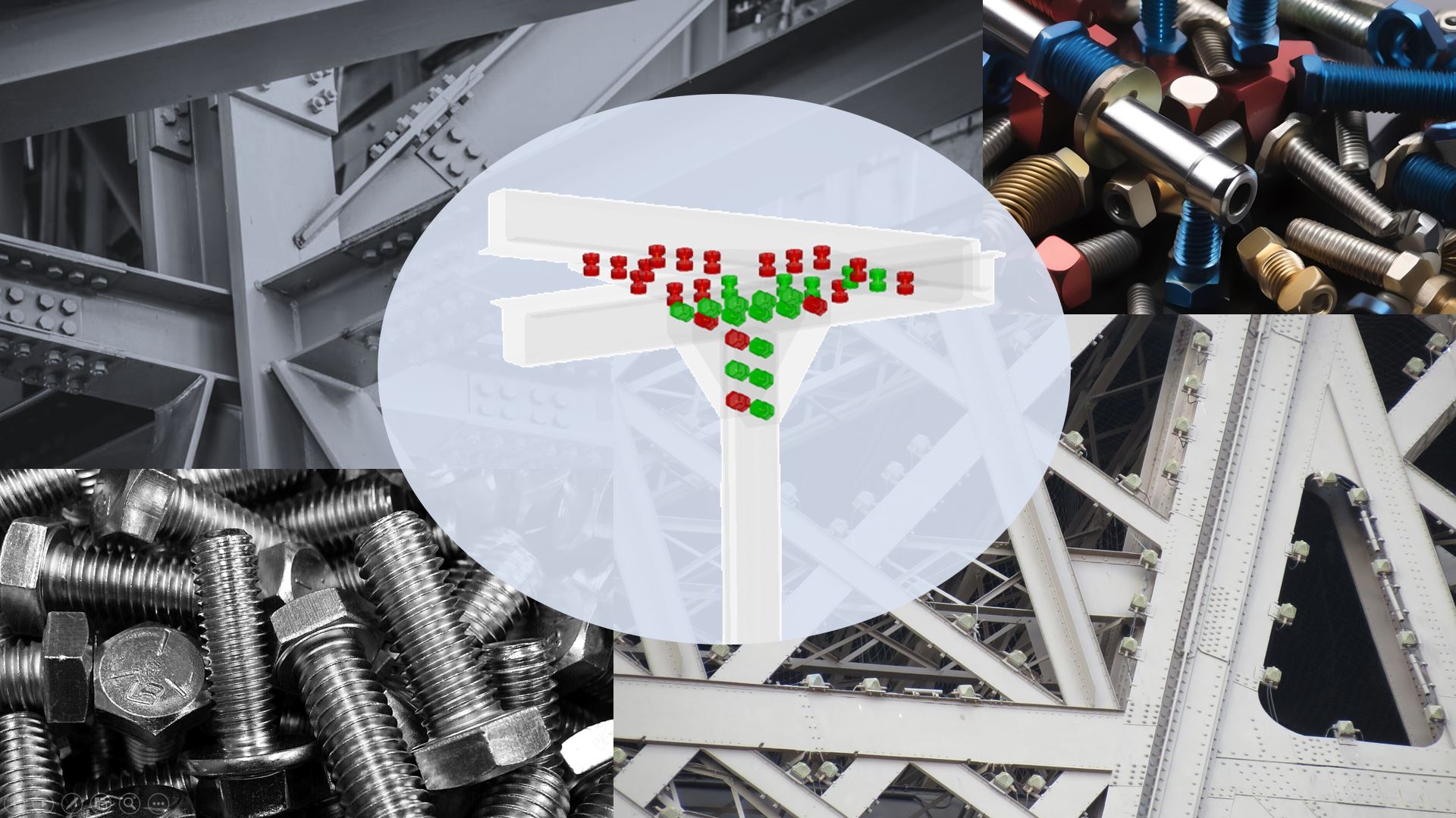
Multi-Bolt Systems

Multi-Bolt Systems

Learn to manage multiple bolts efficiently in your simulations.
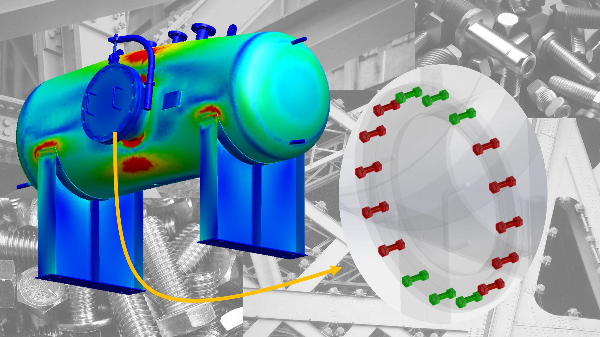
Efficient Tools

Efficient Tools

Use efficient tools to evaluate load transfer and structural integrity in every connection.
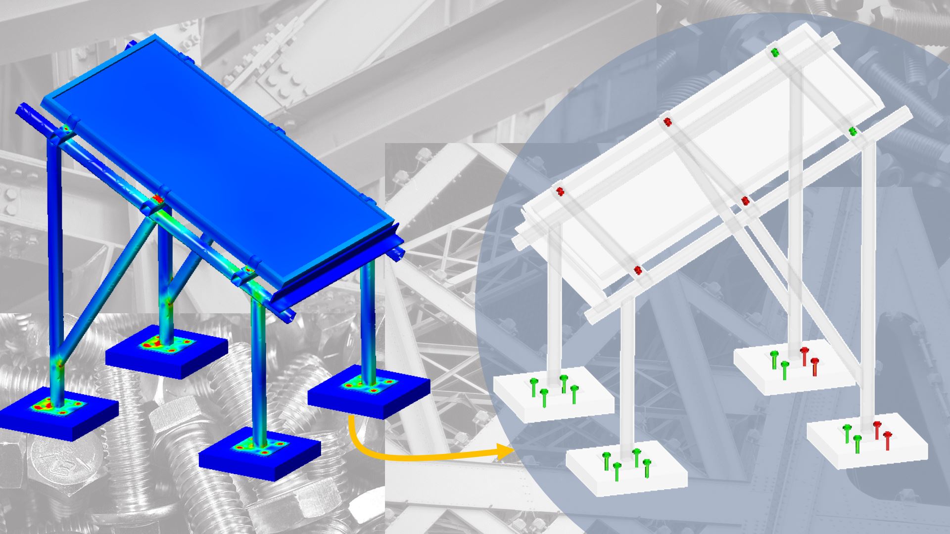
Combined Workflows

Combined Workflows

Combine simulation setups to reflect real engineering workflows.
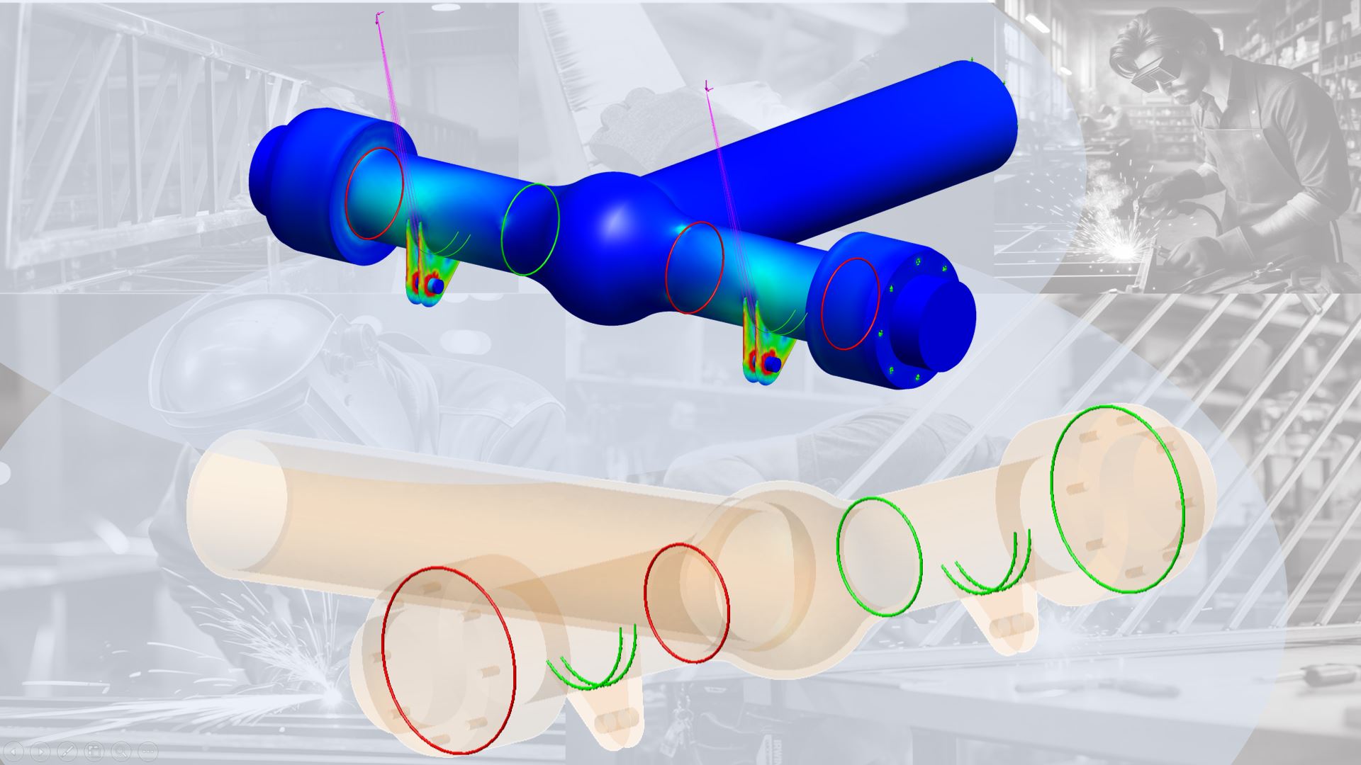
Welding Knowledge

Welding Knowledge

Understand how welded joints behave under real loads.
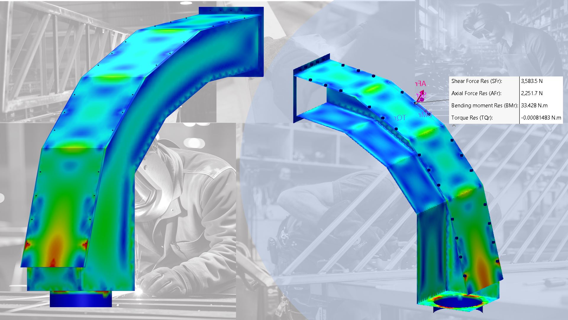
Spot Welding Control

Spot Welding Control

Analyze and optimize spot welds for strength and performance.
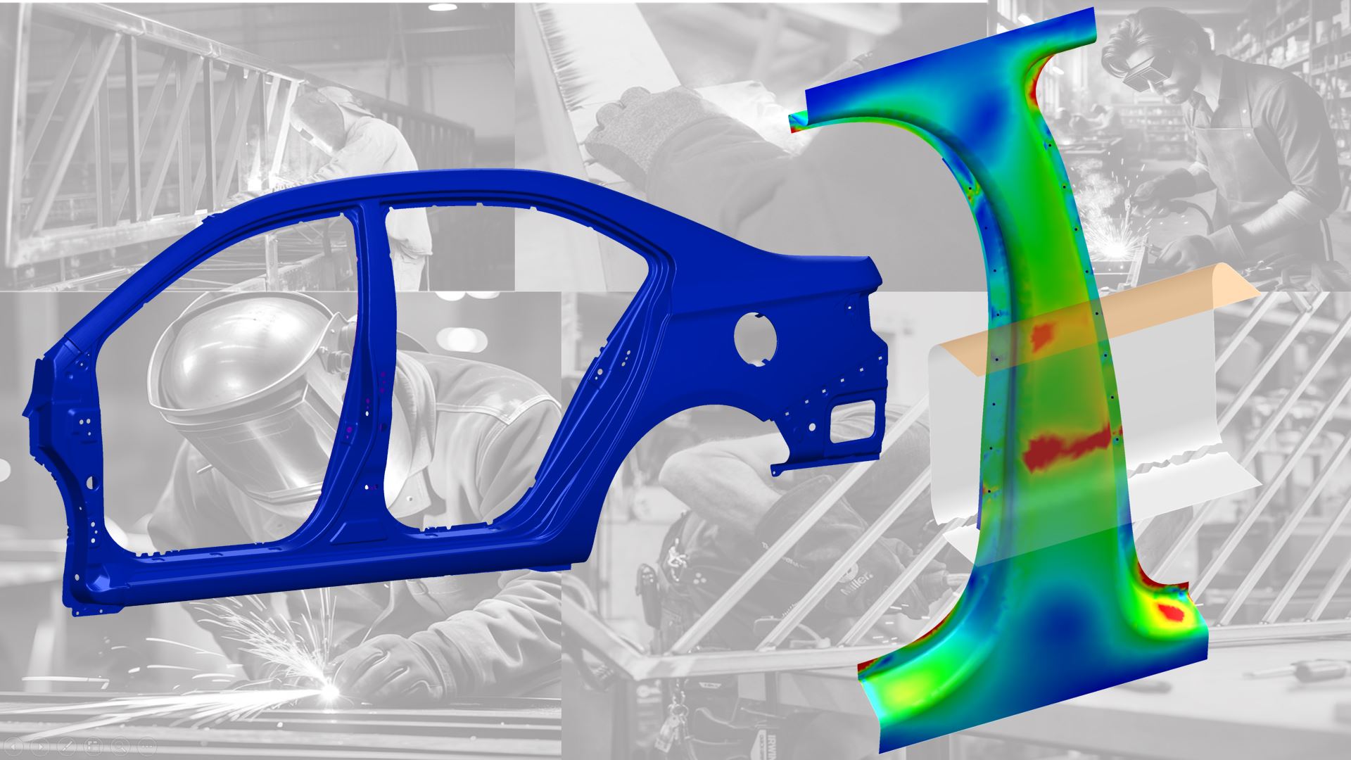
100% Practical Training

100% Practical Training

Apply what you learn directly to real engineering projects.
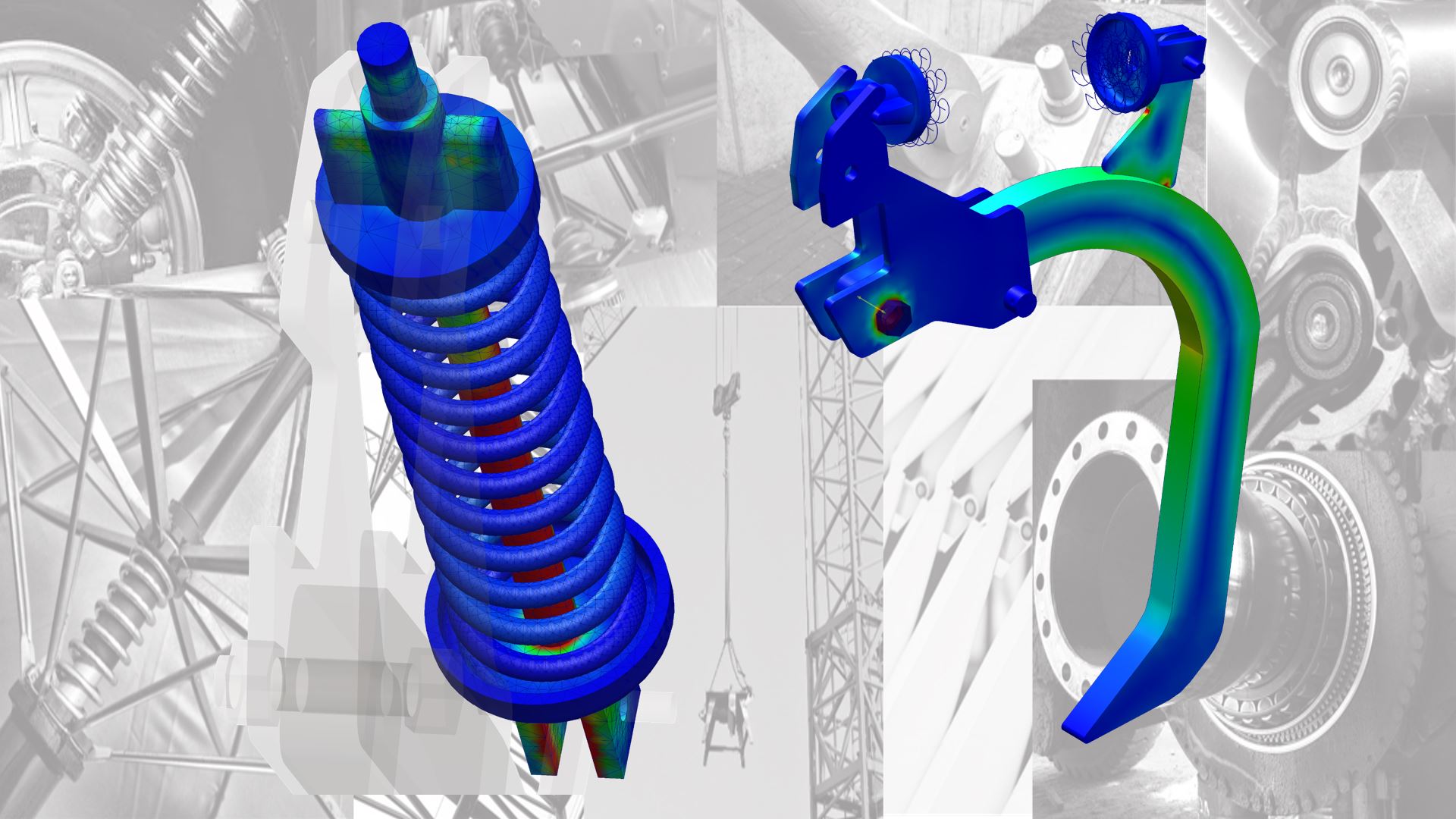
Advanced Connectors

Advanced Connectors

Go beyond the basics and handle more complex simulation scenarios.
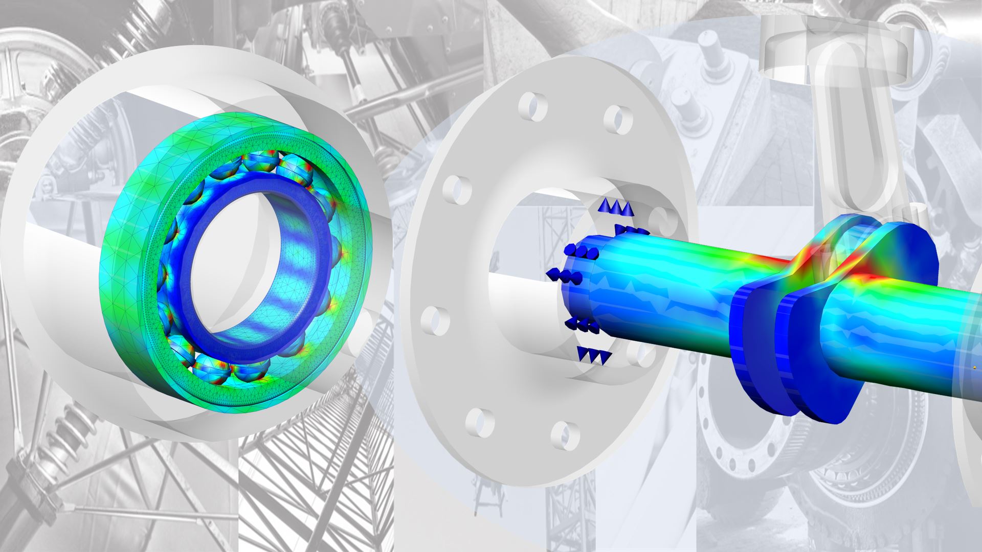
Complex Connections

Complex Connections

Model connections and understand how they affect movement and load transfer.
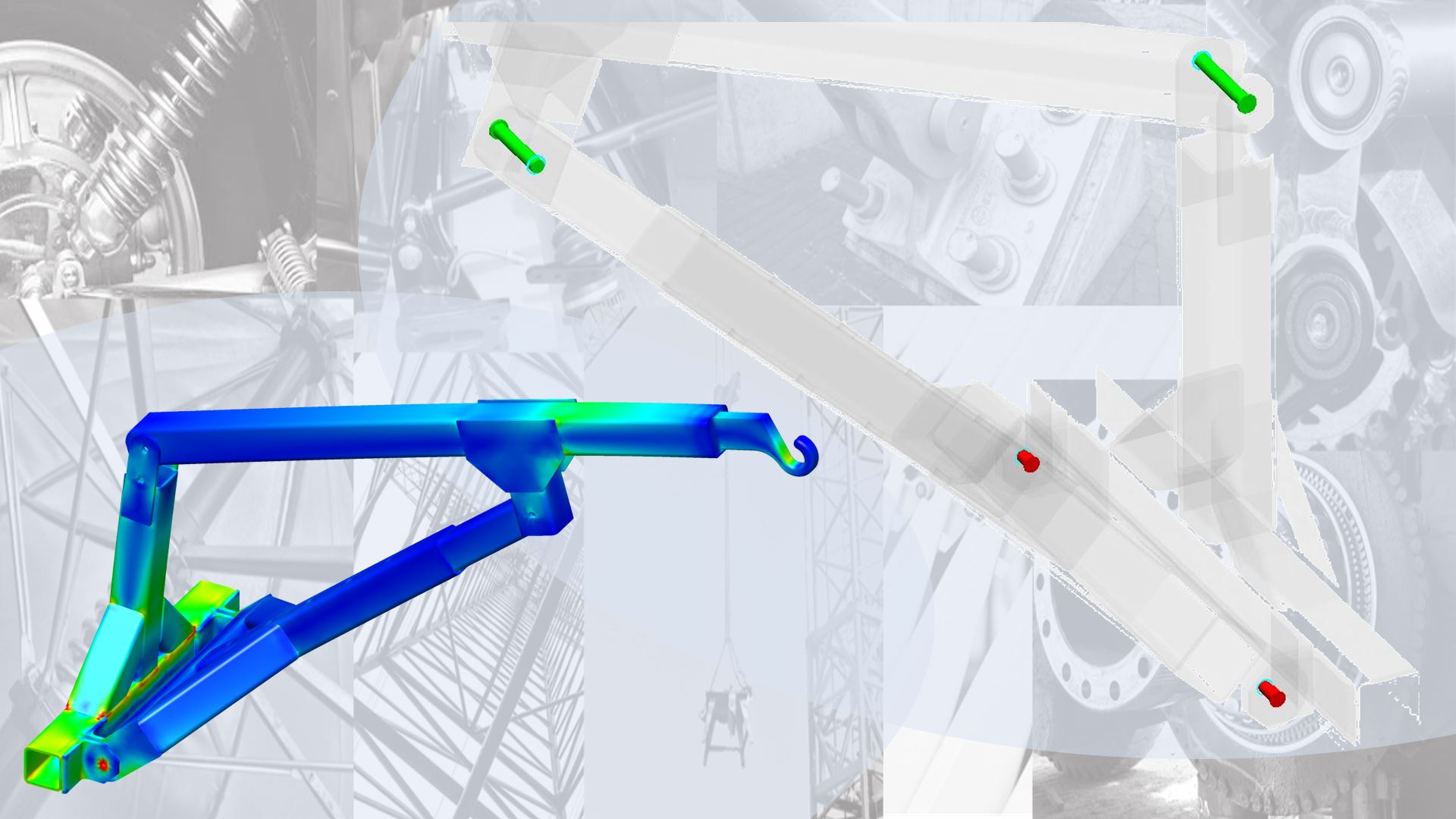
Expand Your FEA Expertise

Expand Your FEA Expertise

Broaden your capabilities across advanced projects and industries.

REAL STUDENTS · REAL RESULTS

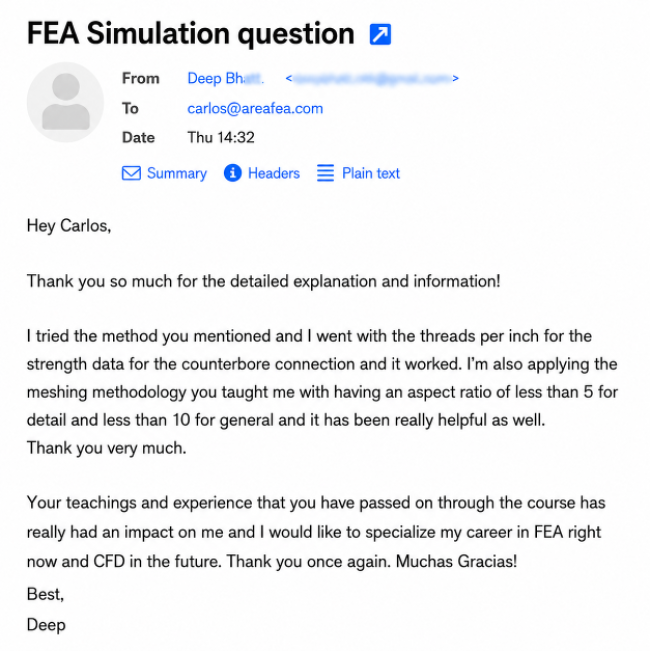
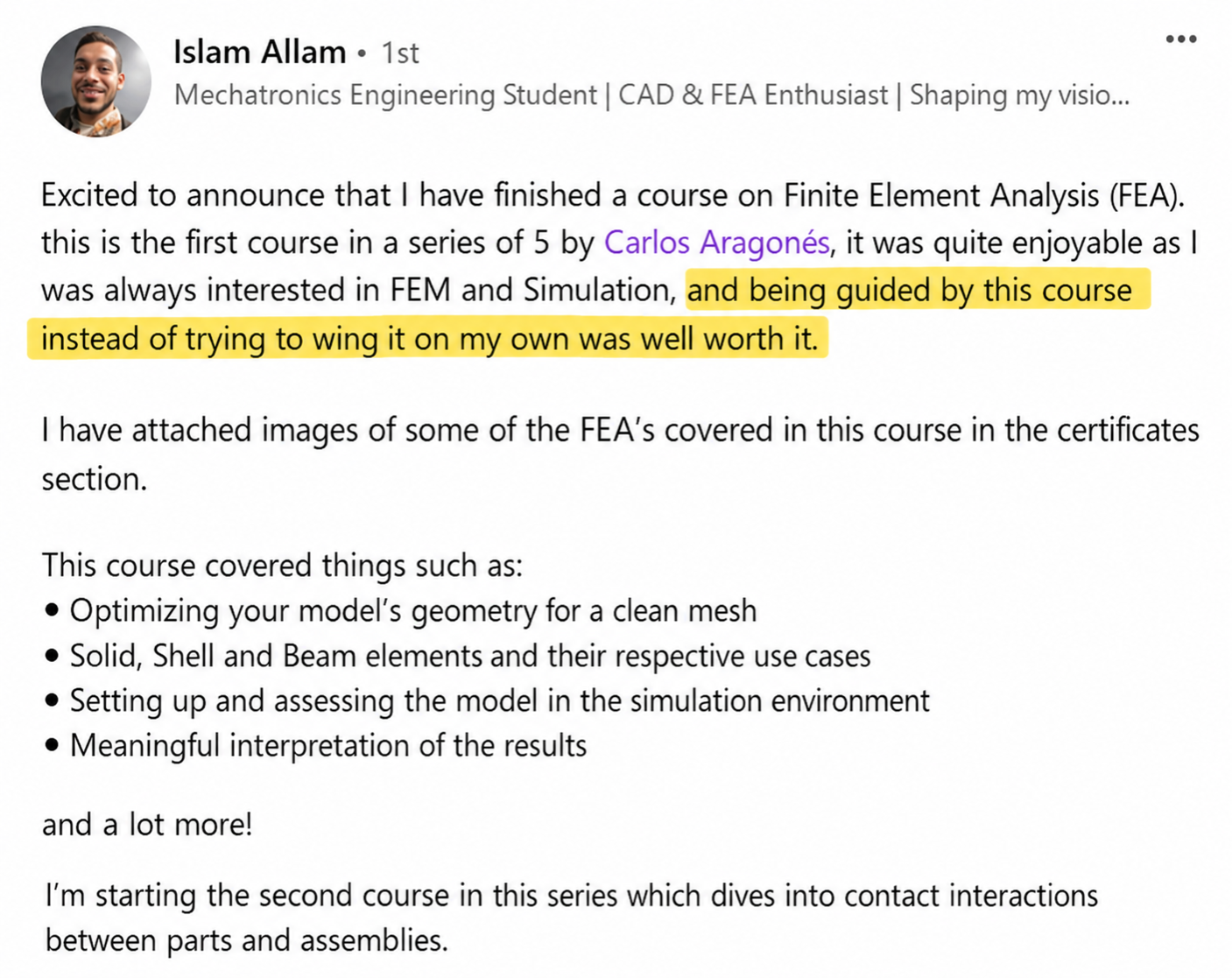
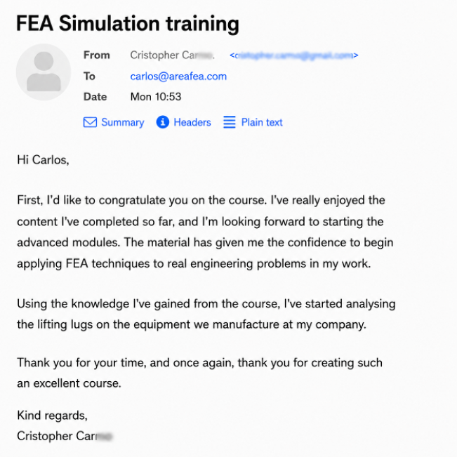
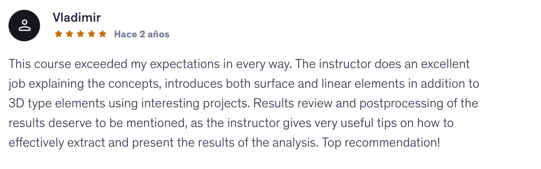
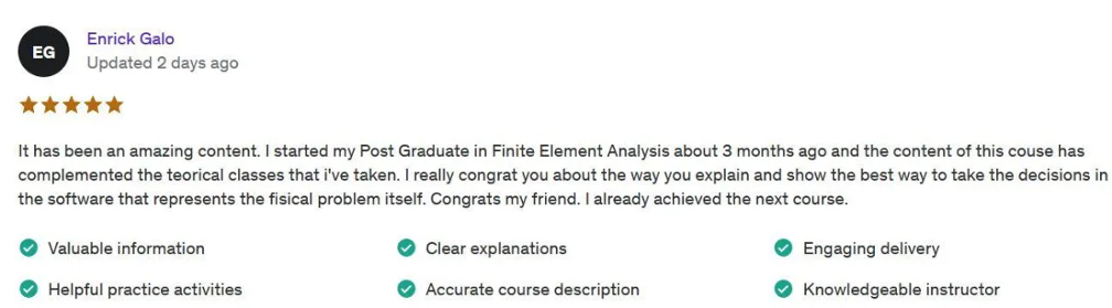
What Students Say About This Approach

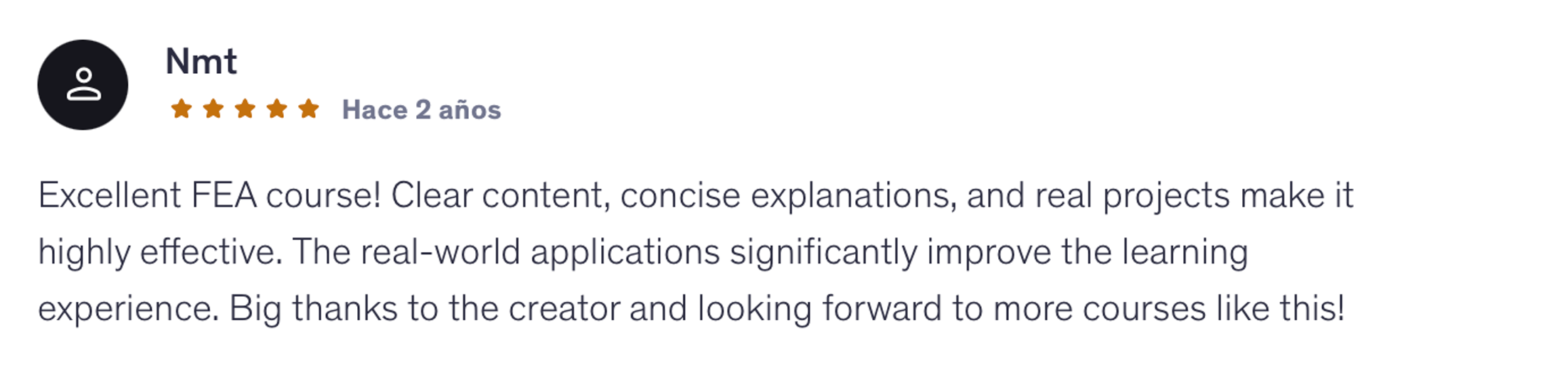
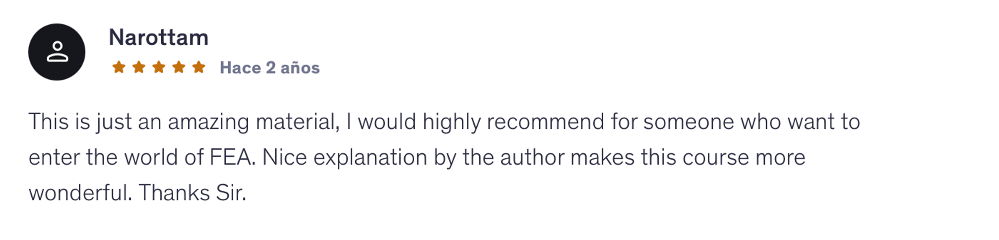
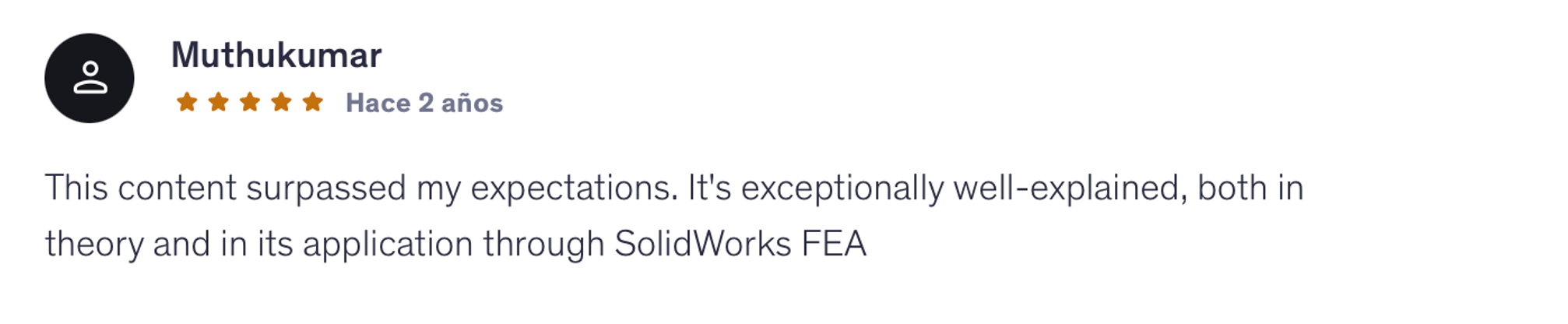
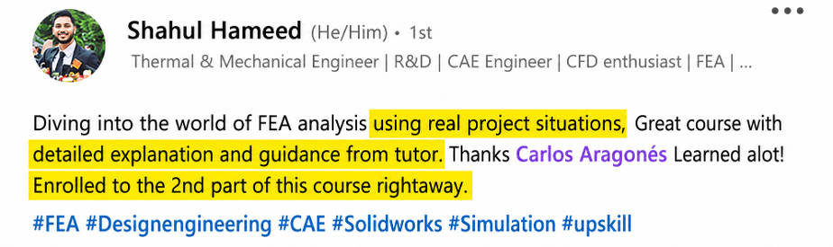
Real feedback from engineers and students who have taken the courses. Click any review to read their full experience
Carlos Aragonés, founder of areaFEA
MEET YOUR INSTRUCTOR

Why I Teach FEA This Way

I'm Carlos Aragonés, founder of areaFEA. I've spent the last 14+ years running finite element simulations on real industrial projects across automotive, energy, and manufacturing, using a wide range of professional FEA platforms.

  • Ansys Mechanical
  • Abaqus
  • NASTRAN
  • SolidWorks Simulation
  • LS-DYNA

The methodology I teach isn't something I learned in a classroom. It's the workflow I built through real engineering projects, refined across thousands of simulations, and now teach to more than 2,300 engineers worldwide.

The software changes. The underlying engineering decisions don’t.

These programs are everything I wish I'd had when I started. They're structured the way industrial work actually happens and built around projects you can defend in a design review.
They're designed to help you understand what to do when you're facing a simulation on your own.

Carlos AragonésMechanical Engineer · 14+ Years in FEA · Founder of areaFEA
ENROLLMENT

Get the Advanced FEA Program.

8 hands-on FEA trainings. Real engineering projects. Unlock your next level in FEA.

Everything Included in Your Enrollment

  • 8 hand-on FEA trainings
  • Real Engineering Projects
  • Downloadable CAD & Simulation Files
  • Immediate Access
  • Lifetime Access
  • Direct Instructor Support
  • Certificates of Completion
ADVANCED FEA PROGRAM
$1,195

Total if purchased separately

SAVE $496
$699

One-time payment. Lifetime access.

Instantaccess
14-daymoney-back guarantee
Securepayment
100% satisfaction guarantee
WE TAKE ALL THE RISK

Try Your Training Risk-Free for 14 Days.

Go through the training and see if it’s right for you. If not, just email us within 14 days and we’ll refund your purchase in full.

  • 14 full days
  • One simple email
  • Full refund
FREQUENT QUESTIONS

Questions Before You Enroll?

Everything you need to know before getting started.

Is this program right for me?

Yes! Whether you're a CAD designer looking to get into simulation, an engineering student, or an engineer looking to improve your FEA skills, this program is designed to help you take the next step.

You'll start with the fundamentals, apply your skills to real engineering projects, and move on to more advanced assembly simulations, building the skills and confidence to tackle more challenging FEA problems.

Do I need prior FEA knowledge?

Not at all! You can start from zero.

The program starts with the FEA fundamentals and gradually moves into more advanced engineering simulations.

If you already have FEA experience, you can strengthen your understanding, fill knowledge gaps, and learn a more consistent approach to solving engineering problems.

What makes areaFEA different from other FEA training programs?

You learn the WHY behind every simulation decision, not just which buttons to click.

The program is built around real engineering projects, not just toy examples. You'll learn how to approach problems, make modelling decisions, and understand your results.

And you'll learn from an FEA expert with 14+ years of industry experience who still works in the field.

Why not just learn FEA from free tutorials?

Free tutorials are a great place to start!

But what happens when your next simulation looks nothing like the example you followed?

Most tutorials focus on solving a specific problem. areaFEA helps you connect the different parts of FEA, understand the decisions behind each simulation, and apply what you've learned to new engineering challenges.

Instead of jumping between disconnected tutorials, you get one complete training program built around real projects.

Will I be able to apply what I learn to my own projects?

That's exactly what areaFEA is designed to help you do.

You won't just work with idealized examples. You'll face real engineering challenges: messy geometries, complex contacts, uncertain loads, meshing problems, and results that don't always make sense.

You'll learn how to approach these situations, understand the decisions behind each simulation, and apply that knowledge to your own engineering projects.

What software do I need?

The program uses SOLIDWORKS Simulation (version 2022 or newer).

Why SOLIDWORKS? It's widely used in engineering and allows us to work directly with CAD models, making it a great tool for learning and applying FEA.

But this program isn't about learning which buttons to click. It's about understanding the engineering decisions behind every simulation.

The methodology you learn applies to other FEA software, including ANSYS, Abaqus, and NASTRAN. The interfaces and specific tools may change, but the fundamental engineering principles remain the same.

The software is the tool. The methodology is the skill.

What if I don't have a SOLIDWORKS license?

Yes! SOLIDWORKS offers an affordable option for independent learners.

For this program, I recommend SOLIDWORKS Design Premium for Students (not the basic Makers version).

It includes SOLIDWORKS Simulation Premium, covering the advanced simulation tools used throughout the training, including bolted connections, contacts, and nonlinear analysis.

You can find more information and get your license at solidworks.com/product/students.

What if I get stuck or have a question during the training?

You're not on your own!

You can ask me directly inside the areaFEA Academy whenever you get stuck, have a question, or need help understanding a simulation.

I personally check the Academy every day, reviewing students' questions and helping them work through their challenges so they can keep moving forward.

When do I get access, and how long does it last?

Immediately! And your access is for life.

As soon as you complete your purchase, you can start learning.

There's no deadline to finish the program. Learn at your own pace, revisit lessons whenever you need them, and return to the training whenever you face new engineering challenges.

What if the program isn't right for me?

You're covered by our 14-day money-back guarantee.

Go through the training and see if it's right for you.

If not, just email us within 14 days of your purchase and we'll refund your payment in full.

One simple email. Full refund.

YOUR NEXT STEP STARTS HERE

Ready to Take Your FEA Skills to the Next Level?

Build the skills and confidence to tackle more challenging simulations, from individual components to complex engineering assemblies.

ENROLL IN ADVANCED FEA PROGRAM

Lifetime Access · 14-Day Money-Back Guarantee